Saturday, 24 March 2012

OSPF Routing - Implementing OSPF over NBMA LAB OBJECTIVE 3


Okay so we are looking good and most of the lab is done, lets see if we can ping from R4 to R5 & R6's loopbacks

Checking the routing table, we know about the loopback interfaces from the two routers ...
 
 R4#show ip route

     1.0.0.0/24 is subnetted, 1 subnets
O IA    1.1.1.0 [110/129] via 10.24.0.2, 00:10:05, Serial0/0.1
     2.0.0.0/24 is subnetted, 1 subnets
O IA    2.2.2.0 [110/65] via 10.24.0.2, 00:10:05, Serial0/0.1
     3.0.0.0/24 is subnetted, 1 subnets
O IA    3.3.3.0 [110/129] via 10.24.0.2, 00:10:05, Serial0/0.1
     4.0.0.0/24 is subnetted, 1 subnets
C       4.4.4.0 is directly connected, Loopback0
     5.0.0.0/24 is subnetted, 1 subnets
O IA    5.5.5.0 [110/193] via 10.24.0.2, 00:03:49, Serial0/0.1
     6.0.0.0/24 is subnetted, 1 subnets
O IA    6.6.6.0 [110/193] via 10.24.0.2, 00:01:40, Serial0/0.1
     10.0.0.0/8 is variably subnetted, 4 subnets, 2 masks
O IA    10.12.3.0/24 [110/128] via 10.24.0.2, 00:10:07, Serial0/0.1
C       10.24.0.0/24 is directly connected, Serial0/0.1
O IA    10.35.6.3/32 [110/128] via 10.24.0.2, 00:06:10, Serial0/0.1
O IA    10.35.6.0/24 [110/256] via 10.24.0.2, 00:03:52, Serial0/0.1


R4#   ping 5.5.5.5

Type escape sequence to abort.
Sending 5, 100-byte ICMP Echos to 5.5.5.5, timeout is 2 seconds:
.....
Success rate is 0 percent (0/5)


R4#ping 6.6.6.6

Type escape sequence to abort.
Sending 5, 100-byte ICMP Echos to 6.6.6.6, timeout is 2 seconds:
.....
Success rate is 0 percent (0/5)


Okay, lets do a traceroute and see where this is going (lets turn off domain-lookup as i dont have DNS configured on these)


R4(config)#no ip domain lookup
R4(config)#do traceroute 5.5.5.5

Type escape sequence to abort.
Tracing the route to 5.5.5.5

  1 10.24.0.2 68 msec 64 msec 28 msec
  2  *  *  *
  3  *  *  *
  4  *


So it looks like are dying at Router2, lets jump over to Router2;

R2#show ip route

     1.0.0.0/24 is subnetted, 1 subnets
O       1.1.1.0 [110/65] via 10.12.3.1, 00:13:48, Serial0/0.1
     2.0.0.0/24 is subnetted, 1 subnets
C       2.2.2.0 is directly connected, Loopback0
     3.0.0.0/24 is subnetted, 1 subnets
O       3.3.3.0 [110/65] via 10.12.3.3, 00:13:48, Serial0/0.1
     4.0.0.0/24 is subnetted, 1 subnets
O       4.4.4.0 [110/65] via 10.24.0.4, 00:17:45, Serial0/1.1
     5.0.0.0/24 is subnetted, 1 subnets
O IA    5.5.5.0 [110/129] via 10.12.3.3, 00:11:30, Serial0/0.1
     6.0.0.0/24 is subnetted, 1 subnets
O IA    6.6.6.0 [110/129] via 10.12.3.3, 00:09:22, Serial0/0.1
     10.0.0.0/8 is variably subnetted, 4 subnets, 2 masks
C       10.12.3.0/24 is directly connected, Serial0/0.1
C       10.24.0.0/24 is directly connected, Serial0/1.1
O IA    10.35.6.3/32 [110/64] via 10.12.3.3, 00:13:51, Serial0/0.1
O IA    10.35.6.0/24 [110/192] via 10.12.3.3, 00:11:34, Serial0/0.1
R2# ping 5.5.5.5

Type escape sequence to abort.
Sending 5, 100-byte ICMP Echos to 5.5.5.5, timeout is 2 seconds:
.....
Success rate is 0 percent (0/5)

Nope, as thought going no where, trace route confirms;


R2(config)#no ip domain loo
R2(config)#do traceroute 5.5.5.5

Type escape sequence to abort.
Tracing the route to 5.5.5.5

  1  *  *


If we look at the routing table again, notice the routes are learnt via 10.12.3.3 ... here lies the problem, as R2 is NOT directly connected to R3, although it believes it is (as being on the same subnet, it would believe it is) but it has to go to R1 first!


As objective 4 says, we cannot add PVCs by modifying the FRS configs, SO .... lets check our map status on the interface

R2#show run int ser0/0.1
interface Serial0/0.1 multipoint
 ip address 10.12.3.2 255.255.255.0
 ip ospf priority 0
 frame-relay map ip 10.12.3.1 201 broadcast
end


We are going to need another frame-relay map statement so that R2 knows what dlci to go to in order to reach R3:


R2(config)#inter seri0/0.1
R2(config-subif)#frame-relay map ip 10.12.3.3 201 broadcast


Now, we need R3 to have a mapping back to R2, same principle:


R3(config)#inter seri0/0.1
R3(config-subif)#frame-relay map ip 10.12.3.2 301 broadcast


thats better:

R3#show frame-relay map
Serial0/0.1 (up): ip 10.12.3.1 dlci 301(0x12D,0x48D0), static,
              broadcast,
              CISCO, status defined, active
Serial0/0.1 (up): ip 10.12.3.2 dlci 301(0x12D,0x48D0), static,
              broadcast,
              CISCO, status defined, active
Serial0/1.1 (up): ip 10.35.6.5 dlci 305(0x131,0x4C10), static,
              broadcast,
              CISCO, status defined, active
Serial0/1.1 (up): ip 10.35.6.6 dlci 306(0x132,0x4C20), static,
              broadcast,
              CISCO, status defined, active


So, lets try that ping again from R4 to R5 & R6
R4# ping 5.5.5.5

Type escape sequence to abort.
Sending 5, 100-byte ICMP Echos to 5.5.5.5, timeout is 2 seconds:
!!!!!
Success rate is 100 percent (5/5), round-trip min/avg/max = 96/143/252 ms


R4#ping 6.6.6.6

Type escape sequence to abort.
Sending 5, 100-byte ICMP Echos to 6.6.6.6, timeout is 2 seconds:
!!!!!
Success rate is 100 percent (5/5), round-trip min/avg/max = 28/129/320 ms


This goes to show and demostrate the network types and the problems/issues that can arise with NBMA


Next Lab ...


Friday, 23 March 2012

OSPF Routing - Implementing OSPF over NBMA LAB


Okay so, below is the lab and as usual all the basic networking is already setup, lets get on with it;

Objectives:
1. Configure OSPF for the above network diagram. You will need to configure OSPF for the Area 0 and Area 24 Frame Relay network using the default OPSF network mode (no ip ospf network statements may be used on any router in these areas). R3’s interface connecting to Area 356 needs to be configured for the OSPF RFC standard point-to-multipoint mode. R5 and R6 must use the default OSPF mode (no ip ospf network statements may be used on R5 or R6).


2. Each OSPF router has a single loopback interface. These should be advertised through the OSPF network. The loopback interfaces of the ABRs can be included in either area.


3. Ensure only appropriate routers have DR/BDR status.


4. In order to achieve full connectivity, you may need to add additional Frame-Relay maps to your routers. However, you may not add additional Frame-Relay PVCs by modifying the FRS devices.


5. To test your configuration, R4 should be able to ping the loopback interfaces of R5 (5.5.5.5) and R6 (6.6.6.6).


Lets get the network advertised and the loopback :0)

R1(config)#router ospf 1
R1(config-router)#network 1.1.1.1 0.0.0.0 area 0
R1(config-router)#network 10.12.3.0 0.0.0.255 area 0
R1(config-router)#router-id 1.1.1.1


Okay, now before we go any further lets check the default modes that the interfaces are in;


R1#show ip ospf interface
Loopback0 is up, line protocol is up
  Internet Address 1.1.1.1/24, Area 0
  Process ID 1, Router ID 1.1.1.1, Network Type POINT_TO_POINT, Cost: 1
  Transmit Delay is 1 sec, State POINT_TO_POINT
  Timer intervals configured, Hello 10, Dead 40, Wait 40, Retransmit 5
    oob-resync timeout 40
  Supports Link-local Signaling (LLS)
  Index 1/1, flood queue length 0
  Next 0x0(0)/0x0(0)
  Last flood scan length is 0, maximum is 0
  Last flood scan time is 0 msec, maximum is 0 msec
  Neighbor Count is 0, Adjacent neighbor count is 0
  Suppress hello for 0 neighbor(s)
Serial0/0.1 is up, line protocol is up
  Internet Address 10.12.3.1/24, Area 0
  Process ID 1, Router ID 1.1.1.1, Network Type NON_BROADCAST, Cost: 64
  Transmit Delay is 1 sec, State DR, Priority 1
  Designated Router (ID) 1.1.1.1, Interface address 10.12.3.1
  No backup designated router on this network
  Timer intervals configured, Hello 30, Dead 120, Wait 120, Retransmit 5
    oob-resync timeout 120
    Hello due in 00:00:06
  Supports Link-local Signaling (LLS)
  Index 2/2, flood queue length 0
  Next 0x0(0)/0x0(0)
  Last flood scan length is 0, maximum is 0
  Last flood scan time is 0 msec, maximum is 0 msec
  Neighbor Count is 0, Adjacent neighbor count is 0
  Suppress hello for 0 neighbor(s)


So if we recall back from the previous post, OSPF over NBMA defaults to NON-BROADCAST which;

  • Is the default mode for x.25, Frame Relay, ATM
  • Neighbours have to be statically configured
  • Must be one subnet
  • Acts like a LAN enviroment 
  • DR/BDR elected (must have FULL connectivity)

(We allow the broadcast on the Frame Network with the sudo broadcast)

Loopback0 is a POINT-TO-POINT becuase i have statically configured it as such, so it doesn't advertise the network as a host address (becuase we want to simulate a network here)

Right, lets get Router2 up;

R2(config-router)#router-id 2.2.2.2
R2(config-router)#network 10.12.3.2 0.0.0.255 area 0
R2(config-router)#network 10.24.0.2 0.0.0.0 area 24
R2(config-router)#network 2.2.2.2 0.0.0.0 area 0


R2#show ip ospf inter
Loopback0 is up, line protocol is up
  Internet Address 2.2.2.2/24, Area 0
  Process ID 1, Router ID 2.2.2.2, Network Type POINT_TO_POINT, Cost: 1
  Transmit Delay is 1 sec, State POINT_TO_POINT
  Timer intervals configured, Hello 10, Dead 40, Wait 40, Retransmit 5
    oob-resync timeout 40
  Supports Link-local Signaling (LLS)
  Index 2/3, flood queue length 0
  Next 0x0(0)/0x0(0)
  Last flood scan length is 0, maximum is 0
  Last flood scan time is 0 msec, maximum is 0 msec
  Neighbor Count is 0, Adjacent neighbor count is 0
  Suppress hello for 0 neighbor(s)
Serial0/0.1 is up, line protocol is up
  Internet Address 10.12.3.2/24, Area 0
  Process ID 1, Router ID 2.2.2.2, Network Type NON_BROADCAST, Cost: 64
  Transmit Delay is 1 sec, State WAITING, Priority 1
  No designated router on this network
  No backup designated router on this network
  Timer intervals configured, Hello 30, Dead 120, Wait 120, Retransmit 5
    oob-resync timeout 120
    Hello due in 00:00:00
    Wait time before Designated router selection 00:00:00
  Supports Link-local Signaling (LLS)
  Index 1/1, flood queue length 0
  Next 0x0(0)/0x0(0)
  Last flood scan length is 0, maximum is 0
  Last flood scan time is 0 msec, maximum is 0 msec
  Neighbor Count is 0, Adjacent neighbor count is 0
  Suppress hello for 0 neighbor(s)
Serial0/1.1 is up, line protocol is up
  Internet Address 10.24.0.2/24, Area 24
  Process ID 1, Router ID 2.2.2.2, Network Type POINT_TO_POINT, Cost: 64
  Transmit Delay is 1 sec, State POINT_TO_POINT
  Timer intervals configured, Hello 10, Dead 40, Wait 40, Retransmit 5
    oob-resync timeout 40
    Hello due in 00:00:08
  Supports Link-local Signaling (LLS)
  Index 1/2, flood queue length 0
  Next 0x0(0)/0x0(0)
  Last flood scan length is 0, maximum is 0
  Last flood scan time is 0 msec, maximum is 0 msec
  Neighbor Count is 0, Adjacent neighbor count is 0
  Suppress hello for 0 neighbor(s)


R2# show run int Serial0/0.1
interface Serial0/0.1 multipoint
 ip address 10.12.3.2 255.255.255.0
 frame-relay map ip 10.12.3.1 201 broadcast
end


R2# show run int Serial0/1.1
interface Serial0/1.1 point-to-point
 ip address 10.24.0.2 255.255.255.0
 frame-relay interface-dlci 204
end


So we can see that the default Multipoint mode for NBMA is NON-BROADCAST - we didn't configure this anywhere!

Also if we look at Serial0/1.1, we can see it recgonised that we configured a subinterface and the OSPF mode defaulted to POINT-2-POINT mode

RIGHT, so the only thing left now is to config R3 and then statically set the neighbours, HOWEVER we need to ensure that Router1 is elected the DR as it is the hub, and R2 and R3 are not elected the BDR's as they do not have FULL connectivity (as this is being treated like a LAN segment) they are just spokes.


R2(config)#inter s0/0.1
R2(config-subif)#ip ospf pri 0


So this makes it so that R2 is NOT a DR, lets do the same on R3 also :0)

R3(config)#inter s0/0.1
R3(config-subif)#ip ospf priority 0


R3(config-subif)#router ospf 1
R3(config-router)#router-id 3.3.3.3
R3(config-router)#network 10.12.3.0 0.0.0.255 area 0
R3(config-router)#network 10.35.6.0 0.0.0.0 area 356
R3(config-router)#network 3.3.3.3 0.0.0.0 area 0


If we check our OSPF neighbours on R1, we still show no neighbours ... so lets set the neighbours statically on R1 (they only need to be set on R1, as R1 will iniate the HELLO with the other two routers and the neighbourship will be formed ....)


R1(config)#router ospf 1
R1(config-router)#neighbor 10.12.3.2 ?
  cost             OSPF cost for point-to-multipoint neighbor
  database-filter  Filter OSPF LSA during synchronization and flooding for
                   point-to-multipoint neighbor
  poll-interval    OSPF dead-router polling interval
  priority         OSPF priority of non-broadcast neighbor
  <cr>


We can set the priority on the neighbours, however priority 0 is the default (so this will not show in the running config)

R1(config-router)#neighbor 10.12.3.2 priority 0
R1(config-router)#neighbor 10.12.3.3 priority 0
R1(config-router)#
*Mar  1 00:43:26.483: %OSPF-5-ADJCHG: Process 1, Nbr 2.2.2.2 on Serial0/0.1 from LOADING to FULL, Loading Done
*Mar  1 00:43:26.631: %OSPF-5-ADJCHG: Process 1, Nbr 3.3.3.3 on Serial0/0.1 from LOADING to FULL, Loading Done


Sweet, OSPF is up and lets just the relationships;


R1#show ip ospf ne

Neighbor ID     Pri   State           Dead Time   Address         Interface
2.2.2.2           0   FULL/DROTHER    00:01:48    10.12.3.2       Serial0/0.1
3.3.3.3           0   FULL/DROTHER    00:01:36    10.12.3.3       Serial0/0.1


Sweet, so we have FULL and both are neither a DR or BDR! lets confirm R1 is the DR:


R1#show ip ospf int serial0/0.1
Serial0/0.1 is up, line protocol is up
  Internet Address 10.12.3.1/24, Area 0
  Process ID 1, Router ID 1.1.1.1, Network Type NON_BROADCAST, Cost: 64
  Transmit Delay is 1 sec, State DR, Priority 1
  Designated Router (ID) 1.1.1.1, Interface address 10.12.3.1
  No backup designated router on this network
  Timer intervals configured, Hello 30, Dead 120, Wait 120, Retransmit 5
    oob-resync timeout 120
    Hello due in 00:00:17
  Supports Link-local Signaling (LLS)
  Index 2/2, flood queue length 0
  Next 0x0(0)/0x0(0)
  Last flood scan length is 1, maximum is 1
  Last flood scan time is 0 msec, maximum is 0 msec
  Neighbor Count is 2, Adjacent neighbor count is 2
    Adjacent with neighbor 2.2.2.2
    Adjacent with neighbor 3.3.3.3
  Suppress hello for 0 neighbor(s)


Double KOOL, whilst this was happening i had a wireshark running in the background, lets see what we got:

The Blue highlighted line is the HELLO packet from R1 to R2, and with the OSPF header you can see all the options that we set! like the PRIORITY the LOOPBACK address and all the timers and address info!!!


You can see that it is sending within the HELLO packet that IT (R1) is the DR ... KEWL!
If we check R2s reply;


And we can see he has acknowledged this is now an ACTIVE neighbour and so can begin exchanging information (LSA's etc):

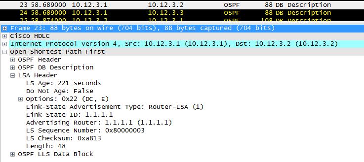
Here we can see the LSA (Link State Advertisement, which is TYPE 1) which is advertising R1's loopback address ... Now here is R2s DB Description packet back to R1;


Notice, we have Summary-LSA (TYPE 3) in there from area 24 which is advertising 10.24.0.0/24, next we see a request from R1 (a LS REQUEST) which is asking for more information about the 2 networks it just recieved LSA's for ....


So R2 then sends out an LS UPDATE (which contains more info about the TYPE1 & TYPE 3 LSA's)


Same process with R3 .... how koool!

Lets setup R4 (our Point-2-Point):

R4(config)#router ospf 1
R4(config-router)#router-id 4.4.4.4
R4(config-router)#network 10.24.0.0 0.0.0.255 area 24
R4(config-router)#network
*Mar  1 01:34:08.243: %OSPF-5-ADJCHG: Process 1, Nbr 2.2.2.2 on Serial0/0.1 from LOADING to FULL, Loading Done
R4(config-router)#network 4.4.4.4 0.0.0.0 area 24


BAM, our neighbour relationship is already up ... BECUASE this is a point to point, so we dont need static neighbours, no BR, DBR (so no election is held) etc:

R4#show ip ospf ne

Neighbor ID     Pri   State           Dead Time   Address         Interface
2.2.2.2           0   FULL/  -        00:00:35    10.24.0.2       Serial0/0.1


R4#show ip ospf int
Loopback0 is up, line protocol is up
  Internet Address 4.4.4.4/24, Area 24
  Process ID 1, Router ID 4.4.4.4, Network Type POINT_TO_POINT, Cost: 1
  Transmit Delay is 1 sec, State POINT_TO_POINT
  Timer intervals configured, Hello 10, Dead 40, Wait 40, Retransmit 5
    oob-resync timeout 40
  Supports Link-local Signaling (LLS)
  Index 2/2, flood queue length 0
  Next 0x0(0)/0x0(0)
  Last flood scan length is 0, maximum is 0
  Last flood scan time is 0 msec, maximum is 0 msec
  Neighbor Count is 0, Adjacent neighbor count is 0
  Suppress hello for 0 neighbor(s)
Serial0/0.1 is up, line protocol is up
  Internet Address 10.24.0.4/24, Area 24
  Process ID 1, Router ID 4.4.4.4, Network Type POINT_TO_POINT, Cost: 64
  Transmit Delay is 1 sec, State POINT_TO_POINT
  Timer intervals configured, Hello 10, Dead 40, Wait 40, Retransmit 5
    oob-resync timeout 40
    Hello due in 00:00:03
  Supports Link-local Signaling (LLS)
  Index 1/1, flood queue length 0
  Next 0x0(0)/0x0(0)
  Last flood scan length is 1, maximum is 1
  Last flood scan time is 0 msec, maximum is 0 msec
  Neighbor Count is 1, Adjacent neighbor count is 1
    Adjacent with neighbor 2.2.2.2
  Suppress hello for 0 neighbor(s)


And lets check the routing table:


R4#show ip route
     1.0.0.0/24 is subnetted, 1 subnets
O IA    1.1.1.0 [110/129] via 10.24.0.2, 00:02:59, Serial0/0.1
     2.0.0.0/24 is subnetted, 1 subnets
O IA    2.2.2.0 [110/65] via 10.24.0.2, 00:02:59, Serial0/0.1
     3.0.0.0/24 is subnetted, 1 subnets
O IA    3.3.3.0 [110/129] via 10.24.0.2, 00:02:59, Serial0/0.1
     4.0.0.0/24 is subnetted, 1 subnets
C       4.4.4.0 is directly connected, Loopback0
     10.0.0.0/24 is subnetted, 2 subnets
O IA    10.12.3.0 [110/128] via 10.24.0.2, 00:02:59, Serial0/0.1
C       10.24.0.0 is directly connected, Serial0/0.1


SO in Objective 1, we need to address this part
"R3’s interface connecting to Area 356 needs to be configured for the OSPF RFC standard point-to-multipoint mode"
 
R3(config-router)#inter s0/1.1
R3(config-subif)#ip ospf network point-to-multipoint


Lets check it:

Serial0/1.1 is up, line protocol is up
  Internet Address 10.35.6.3/24, Area 356
  Process ID 1, Router ID 3.3.3.3, Network Type POINT_TO_MULTIPOINT, Cost: 64
  Transmit Delay is 1 sec, State POINT_TO_MULTIPOINT
  Timer intervals configured, Hello 30, Dead 120, Wait 120, Retransmit 5
    oob-resync timeout 120
    Hello due in 00:00:28
  Supports Link-local Signaling (LLS)
  Index 1/3, flood queue length 0
  Next 0x0(0)/0x0(0)
  Last flood scan length is 0, maximum is 0
  Last flood scan time is 0 msec, maximum is 0 msec
  Neighbor Count is 0, Adjacent neighbor count is 0
  Suppress hello for 0 neighbor(s)


Excellent, lets get R5 and R6 setup:


R5(config)#router ospf 1
R5(config-router)#router-id 5.5.5.5
R5(config-router)#network 5.5.5.5 0.0.0.0 area 356
R5(config-router)#network 10.35.6.0 0.0.0.255 area 356


 MMmm but no neighbours, YET we are a point to multipoint, we dont have to configure static neighbours


R5#show ip ospf int
Loopback0 is up, line protocol is up
  Internet Address 5.5.5.5/24, Area 356
  Process ID 1, Router ID 5.5.5.5, Network Type POINT_TO_POINT, Cost: 1
  Transmit Delay is 1 sec, State POINT_TO_POINT
  Timer intervals configured, Hello 10, Dead 40, Wait 40, Retransmit 5
    oob-resync timeout 40
  Supports Link-local Signaling (LLS)
  Index 1/1, flood queue length 0
  Next 0x0(0)/0x0(0)
  Last flood scan length is 0, maximum is 0
  Last flood scan time is 0 msec, maximum is 0 msec
  Neighbor Count is 0, Adjacent neighbor count is 0
  Suppress hello for 0 neighbor(s)
Serial0/0.1 is up, line protocol is up
  Internet Address 10.35.6.5/24, Area 356
  Process ID 1, Router ID 5.5.5.5, Network Type POINT_TO_POINT, Cost: 64
  Transmit Delay is 1 sec, State POINT_TO_POINT
  Timer intervals configured, Hello 10, Dead 40, Wait 40, Retransmit 5
    oob-resync timeout 40
    Hello due in 00:00:04
  Supports Link-local Signaling (LLS)
  Index 2/2, flood queue length 0
  Next 0x0(0)/0x0(0)


R5#show run int Serial0/0.1
interface Serial0/0.1 point-to-point
 ip address 10.35.6.5 255.255.255.0
 frame-relay interface-dlci 503


The default mode for point-to-point is point-2-point, not multipoint ... R3 is the hub and has the connectivity to reach both R5 and R6 ....


If we check R3's serial interface:


R3#show ip ospf int Serial0/1.1
Serial0/1.1 is up, line protocol is up
  Internet Address 10.35.6.3/24, Area 356
  Process ID 1, Router ID 3.3.3.3, Network Type POINT_TO_MULTIPOINT, Cost: 64
  Transmit Delay is 1 sec, State POINT_TO_MULTIPOINT
  Timer intervals configured, Hello 30, Dead 120, Wait 120, Retransmit 5


compare this against R5 serials interface:


Serial0/0.1 is up, line protocol is up
  Internet Address 10.35.6.5/24, Area 356
  Process ID 1, Router ID 5.5.5.5, Network Type POINT_TO_POINT, Cost: 64
  Transmit Delay is 1 sec, State POINT_TO_POINT
  Timer intervals configured, Hello 10, Dead 40, Wait 40, Retransmit 5


One thing that MUST match when forming neighbours is the HELLO timers!


If i adjust the HELLO timer on R3 to match R5
R3(config)#int Serial0/1.1
R3(config-subif)#ip ospf hello-interval 10
R3(config-subif)#
*Mar  1 02:02:36.687: %OSPF-5-ADJCHG: Process 1, Nbr 5.5.5.5 on Serial0/1.1 from LOADING to FULL, Loading Done


The dead timer is automagically adusted to x4 times the hello timer

R3#show ip ospf ne

Neighbor ID     Pri   State           Dead Time   Address         Interface
1.1.1.1           1   FULL/DR         00:01:51    10.12.3.1       Serial0/0.1
5.5.5.5           0   FULL/  -        00:00:35    10.35.6.5       Serial0/1.1


Lets do R6, i should not need to adjust anything for R6, as we have changed the HUB interface on R3


R6(config)#router ospf 1
R6(config-router)#router-id 6.6.6.6
R6(config-router)#network 10.35.6.6 0.0.0.0 area 356
*Mar  1 02:05:29.979: %OSPF-5-ADJCHG: Process 1, Nbr 3.3.3.3 on Serial0/0.1 from LOADING to FULL, Loading Done
R6(config-router)#network 6.6.6.6 0.0.0.0 area 356
R6(config-router)#exit


R6(config)#do show ip ospf ne

Neighbor ID     Pri   State           Dead Time   Address         Interface
3.3.3.3           0   FULL/  -        00:00:37    10.35.6.3       Serial0/0.1


R6(config)#do show ip ospf ne

Neighbor ID     Pri   State           Dead Time   Address         Interface
3.3.3.3           0   FULL/  -        00:00:37    10.35.6.3       Serial0/0.1


Excellent, lets check the routing table:


R6(config)#do show ip route

     1.0.0.0/24 is subnetted, 1 subnets
O IA    1.1.1.0 [110/129] via 10.35.6.3, 00:01:40, Serial0/0.1
     2.0.0.0/24 is subnetted, 1 subnets
O IA    2.2.2.0 [110/129] via 10.35.6.3, 00:01:40, Serial0/0.1
     3.0.0.0/24 is subnetted, 1 subnets
O IA    3.3.3.0 [110/65] via 10.35.6.3, 00:01:40, Serial0/0.1
     4.0.0.0/24 is subnetted, 1 subnets
O IA    4.4.4.0 [110/193] via 10.35.6.3, 00:01:40, Serial0/0.1
     5.0.0.0/24 is subnetted, 1 subnets
O       5.5.5.0 [110/129] via 10.35.6.3, 00:01:40, Serial0/0.1
     6.0.0.0/24 is subnetted, 1 subnets
C       6.6.6.0 is directly connected, Loopback0
     10.0.0.0/8 is variably subnetted, 4 subnets, 2 masks
O IA    10.12.3.0/24 [110/128] via 10.35.6.3, 00:01:43, Serial0/0.1
O IA    10.24.0.0/24 [110/192] via 10.35.6.3, 00:01:43, Serial0/0.1
O       10.35.6.3/32 [110/64] via 10.35.6.3, 00:01:43, Serial0/0.1
C       10.35.6.0/24 is directly connected, Serial0/0.1


Okay, so we have now completed upto Objective 3 .... the rest to follow tomorrow


Wow, check this guy out over at : http://www.ine.com/about-petr.htm
"is the only person in the world to have obtained four CCIEs in under two year"


AWESOME, STUFF, just what i need for some more motivation!

Saturday, 17 March 2012

12 - OSPF Routing - Implementing OSPF over NBMA 1

Lets go over and cover the network types:


Hub and Spoke (Star)
Most cost effective (cheapest) but major draw backs are reduancy and LATENCY is a big hit, ecspecially on VoIP and delay, sensitive traffic!


Partial MESH

Only the major Sites have meshing and less important sites do not
Full MESG
Very expensive, but with newer technologies such as MPLS or PIVPN not such a big deal,
however we are not focusing on the technology at this point :oP

SO the MODES:
Well we have already covered and implemented 2 of the 5 modes;


Additional notes:
Here it acts just like it was an ethernet segment, but over the WAN instead, we have
multicast messages, we elect a DR and BDR ... BUT we have the neighbours set statically,

Also the DR and BDR ... it has to be R4, as both R2 and R3 do not have full connectivity and because of this will form a FULL relationship with R4 (however if this was a full mesh
then it would not matter who was DR and BDR as everyone would form a FULL relationship and this would be just like a ethernet segment)


But with partial mesh or hub and spoke you need to get involved and tweak it alittle

So, R4 will exchange routes with neighbours on 224.0.0.6 and then send the msgs back out on 224.0.0.5


But this depends on your network topology! If we take the example below a single subnet does not make sense here .... so you could  ...

Here we have chosen a different mode of OSPF for the 2 companies below who have just a PVC running between them, you can mix and match the modes!

The goal is to get these guys exchanging routes and forming neighbours over our NBMA cloud, so the point-2-multipoint is just another tool to make it happen :0)


Makes connections work exactly like point to point (multicast to 224.0.0.5) ...no DR and BDR
but its over NBMA,
ONLY DRAWBACK,. you need a unique subnet per neighbour that you are using over the cloud

Monday, 12 March 2012

IMPLEMENTING BASIC OSPF


Core OSPF Configuration
Route Summarisation
DR Election
OSPF cost calculation


OBJECTIVE 1

Configure OSPF for the above network diagram. R1 will act as an ASBR by redistributing a series of static routes into the OSPF network. These routes should NOT increment their metric as they pass through the network and should have an initial OSPF cost of 200. All routers should have a router-id reflecting their hostname; you should be able to ping this router-id throughout the entire OSPF network.


Lets start off with Router1 and get OSPF up and running (I have already configured the basic networking)


R1(config)#router ospf 1
R1(config-router)#network 172.30.0.1 0.0.0.0 area 0
R1(config-router)#router-id 1.1.1.1

As mentioned before, it is worth while specifying the router-id now, rather than after the OSPF neighbourship as once it has formed you would have to clear the OSPF process or reboot the router(s) - by default it would of chosen the loopback interface as the RID

Lets setup the redistribution of the static routes into OSPF

R1(config-router)#redistribute static subnets


DONT forget the metric ...

R1(config-router)#redistribute static subnets metric ?
  <0-16777214>  OSPF default metric


We also need to specify the seed metric that these routes will start off with (looking at the objective it is 200)

and they must not increment when prograting thru the network (remember this from EIGRP/OSPF redistributition ...)

By default they are E2 routes which do not increment, E1 routes doo incriment

WHY AND WHEN TO USE WHICH METRIC-TYPE
Since our ASBR is the only exit point for these OSPF routes ... it doesnt matter which way the routers go to get to it, So their is no point the routers taking CPU cycles doing all the math, however if we had another exit point for them, then we would want the intelligence in the route decisions and we would use E1 routes


R1(config-router)#redistribute static subnets metric 200


Lets get our neighbours up and running ..

R2(config)#router ospf 1
R2(config-router)#network 172.30.0.2 0.0.0.0 area 0
R2(config-router)#network 172.30.10.2 0.0.0.0 area 10

*Mar  1 00:50:53.083: %OSPF-5-ADJCHG: Process 1, Nbr 1.1.1.1 on FastEthernet0/0 from LOADING to FULL, Loading Done


R2#show ip ospf ne

Neighbor ID     Pri   State           Dead Time   Address         Interface
1.1.1.1           1   FULL/DR         00:00:39    172.30.0.1      FastEthernet0/0


Lets check R1;

R1#show ip ospf ne

Neighbor ID     Pri   State           Dead Time   Address         Interface
172.30.10.2       1   FULL/BDR        00:00:33    172.30.0.2      FastEthernet0/0


Ah, yes notice the RID, lets try and change it:

R2(config)#router ospf 1
R2(config-router)#router-id 2.2.2.2
Reload or use "clear ip ospf process" command, for this to take effect


Soooo...

R2#clear ip ospf process
Reset ALL OSPF processes? [no]: y
R2#y
*Mar  1 01:01:06.835: %OSPF-5-ADJCHG: Process 1, Nbr 1.1.1.1 on FastEthernet0/0 from FULL to DOWN, Neighbor Down: Interface down or detached


R1#show ip ospf ne

Neighbor ID     Pri   State           Dead Time   Address         Interface
2.2.2.2           1   FULL/BDR        00:00:38    172.30.0.2      FastEthernet0/0


and lets check for that route from area 10;

R1#show ip route

     172.16.0.0/24 is subnetted, 4 subnets
S       172.16.0.0 is directly connected, Null0
S       172.16.1.0 is directly connected, Null0
S       172.16.2.0 is directly connected, Null0
S       172.16.3.0 is directly connected, Null0
     172.30.0.0/24 is subnetted, 2 subnets
C       172.30.0.0 is directly connected, FastEthernet0/0
O IA    172.30.10.0 [110/210] via 172.30.0.2, 00:00:30, FastEthernet0/0


Also R2 has got the static routes with their new cost of 200 (and notice the E2 flag);

R2#show ip route
     172.16.0.0/24 is subnetted, 4 subnets
O E2    172.16.0.0 [110/200] via 172.30.0.1, 00:00:09, FastEthernet0/0
O E2    172.16.1.0 [110/200] via 172.30.0.1, 00:00:09, FastEthernet0/0
O E2    172.16.2.0 [110/200] via 172.30.0.1, 00:00:09, FastEthernet0/0
O E2    172.16.3.0 [110/200] via 172.30.0.1, 00:00:09, FastEthernet0/0
     172.30.0.0/24 is subnetted, 2 subnets
C       172.30.0.0 is directly connected, FastEthernet0/0
C       172.30.10.0 is directly connected, Serial0/0


 Lets do R3;

R3(config)#router ospf 1
R3(config-router)#router-id 3.3.3.3
R3(config-router)#network 172.30.0.3 0.0.0.0 area 0
R3(config-router)#
*Mar  1 01:10:19.827: %OSPF-5-ADJCHG: Process 1, Nbr 2.2.2.2 on FastEthernet0/0 from LOADING to FULL, Loading Done
R3(config-router)#
*Mar  1 01:10:25.883: %OSPF-5-ADJCHG: Process 1, Nbr 1.1.1.1 on FastEthernet0/0 from LOADING to FULL, Loading Done
R3(config-router)#network 172.30.20.3 0.0.0.0 area 20


Lets check his router table:


R3#show ip route

     172.16.0.0/24 is subnetted, 4 subnets
O E2    172.16.0.0 [110/200] via 172.30.0.1, 00:01:36, FastEthernet0/0
O E2    172.16.1.0 [110/200] via 172.30.0.1, 00:01:36, FastEthernet0/0
O E2    172.16.2.0 [110/200] via 172.30.0.1, 00:01:36, FastEthernet0/0
O E2    172.16.3.0 [110/200] via 172.30.0.1, 00:01:36, FastEthernet0/0
     172.30.0.0/24 is subnetted, 3 subnets
C       172.30.20.0 is directly connected, Serial0/0
C       172.30.0.0 is directly connected, FastEthernet0/0
O IA    172.30.10.0 [110/210] via 172.30.0.2, 00:01:37, FastEthernet0/0


lets do R4

R4(config)#router ospf 1
R4(config-router)#router-id 4.4.4.4
R4(config-router)#network 10.0.0.0 0.255.255.255 area 20
R4(config-router)#network 172.30.20.4 0.0.0.0 area 20
R4(config-router)#
*Mar  1 01:16:29.455: %OSPF-5-ADJCHG: Process 1, Nbr 3.3.3.3 on Serial0/0 from LOADING to FULL, Loading Done
R4(config-router)#


R4#show ip route

     172.16.0.0/24 is subnetted, 4 subnets
O E2    172.16.0.0 [110/200] via 172.30.20.3, 00:00:40, Serial0/0
O E2    172.16.1.0 [110/200] via 172.30.20.3, 00:00:40, Serial0/0
O E2    172.16.2.0 [110/200] via 172.30.20.3, 00:00:40, Serial0/0
O E2    172.16.3.0 [110/200] via 172.30.20.3, 00:00:40, Serial0/0
     172.30.0.0/24 is subnetted, 3 subnets
C       172.30.20.0 is directly connected, Serial0/0
O IA    172.30.0.0 [110/210] via 172.30.20.3, 00:00:40, Serial0/0    (Area 0)
O IA    172.30.10.0 [110/410] via 172.30.20.3, 00:00:42, Serial0/0  (Area 10)
     10.0.0.0/24 is subnetted, 4 subnets
C       10.20.2.0 is directly connected, Loopback3
C       10.20.3.0 is directly connected, Loopback4
C       10.20.0.0 is directly connected, Loopback1
C       10.20.1.0 is directly connected, Loopback2


and R5;
R5(config)#router ospf 1
R5(config-router)#router-id 5.5.5.5
R5(config-router)#network 172.30.10.5 0.0.0.0 area 10
R5(config-router)#network 10.10.0.0 0.0.255.255 area 10


We now have our new neighbour up and running;

R5#show ip route

     172.16.0.0/24 is subnetted, 4 subnets
O E2    172.16.0.0 [110/200] via 172.30.10.2, 00:07:25, Serial0/0
O E2    172.16.1.0 [110/200] via 172.30.10.2, 00:07:25, Serial0/0
O E2    172.16.2.0 [110/200] via 172.30.10.2, 00:07:25, Serial0/0
O E2    172.16.3.0 [110/200] via 172.30.10.2, 00:07:25, Serial0/0
     172.30.0.0/24 is subnetted, 3 subnets
O IA    172.30.20.0 [110/410] via 172.30.10.2, 00:07:25, Serial0/0
O IA    172.30.0.0 [110/210] via 172.30.10.2, 00:07:25, Serial0/0
C       172.30.10.0 is directly connected, Serial0/0
     10.0.0.0/8 is variably subnetted, 8 subnets, 2 masks
C       10.10.0.0/24 is directly connected, Loopback1
C       10.10.1.0/24 is directly connected, Loopback2
C       10.10.2.0/24 is directly connected, Loopback3
C       10.10.3.0/24 is directly connected, Loopback4
O IA    10.20.3.1/32 [110/411] via 172.30.10.2, 00:07:28, Serial0/0
O IA    10.20.2.1/32 [110/411] via 172.30.10.2, 00:07:28, Serial0/0
O IA    10.20.1.1/32 [110/411] via 172.30.10.2, 00:07:28, Serial0/0
O IA    10.20.0.1/32 [110/411] via 172.30.10.2, 00:07:28, Serial0/0


Although, in the normal working world having them loopbacks advertised as /32 is normal (even though i have configured them as a /24, OSPF is clever enough to not get fooled and shows it as the 1 address, but since we are in a lab enviroment we can tweak it, as i have shown you before to look like a /24 network)

R5(config)#int loo 1
R5(config-if)#ip ospf network point-to-point
R5(config)#inte loo 2
R5(config-if)#ip ospf network point-to-point
R5(config-if)#inte loo 3
R5(config-if)#ip ospf network point-to-point
R5(config-if)#inte loo 4
R5(config-if)#ip ospf network point-to-point


R4(config)#int loo 1
R4(config-if)#ip ospf network point-to-point
R4(config-if)#int loo 2
R4(config-if)#ip ospf network point-to-point
R4(config-if)#int loo 3
R4(config-if)#ip ospf network point-to-point
R4(config-if)#int loo 4
R4(config-if)#ip ospf network point-to-point


R1#show ip route


     172.16.0.0/24 is subnetted, 4 subnets
S       172.16.0.0 is directly connected, Null0
S       172.16.1.0 is directly connected, Null0
S       172.16.2.0 is directly connected, Null0
S       172.16.3.0 is directly connected, Null0
     172.30.0.0/24 is subnetted, 3 subnets
O IA    172.30.20.0 [110/210] via 172.30.0.3, 00:23:05, FastEthernet0/0
C       172.30.0.0 is directly connected, FastEthernet0/0
O IA    172.30.10.0 [110/210] via 172.30.0.2, 00:23:05, FastEthernet0/0
     10.0.0.0/24 is subnetted, 8 subnets
O IA    10.10.0.0 [110/211] via 172.30.0.2, 00:07:09, FastEthernet0/0
O IA    10.10.1.0 [110/211] via 172.30.0.2, 00:04:38, FastEthernet0/0
O IA    10.10.2.0 [110/211] via 172.30.0.2, 00:04:28, FastEthernet0/0
O IA    10.10.3.0 [110/211] via 172.30.0.2, 00:04:29, FastEthernet0/0
O IA    10.20.2.0 [110/211] via 172.30.0.3, 00:02:06, FastEthernet0/0
O IA    10.20.3.0 [110/211] via 172.30.0.3, 00:02:06, FastEthernet0/0
O IA    10.20.0.0 [110/211] via 172.30.0.3, 00:02:16, FastEthernet0/0
O IA    10.20.1.0 [110/211] via 172.30.0.3, 00:02:16, FastEthernet0/0


THATS BETTER :0) ... okay thats STEP 1 COMPLETE


OBJECTIVE 2.

After completing the initial step of the lab, one of the routers in Area 0 will become the DR and one will become the BDR for the Ethernet segment. Which router will become the DR and BDR? Write DR and BDR next to the respective router below.
o R1
o R2
o R3

Well, lets just reset the process as currently the order i booted these bad bois will affect the results, so..


R1#clear ip ospf process
Reset ALL OSPF processes? [no]: y
R1#
*Mar  1 00:35:35.159: %OSPF-5-ADJCHG: Process 1, Nbr 2.2.2.2 on FastEthernet0/0 from FULL to DOWN, Neighbor Down: Interface down or detached
*Mar  1 00:35:35.163: %OSPF-5-ADJCHG: Process 1, Nbr 3.3.3.3 on FastEthernet0/0 from FULL to DOWN, Neighbor Down: Interface down or detached
*Mar  1 00:35:35.347: %OSPF-5-ADJCHG: Process 1, Nbr 2.2.2.2 on FastEthernet0/0 from LOADING to FULL, Loading Done
*Mar  1 00:35:35.351: %OSPF-5-ADJCHG: Process 1, Nbr 3.3.3.3 on FastEthernet0/0 from LOADING to FULL, Loading Done

Lets have a look and see what we have:

R1#show ip ospf interface
FastEthernet0/0 is up, line protocol is up
  Internet Address 172.30.0.1/24, Area 0
  Process ID 1, Router ID 1.1.1.1, Network Type BROADCAST, Cost: 10
  Transmit Delay is 1 sec, State DROTHER, Priority 1
  Designated Router (ID) 3.3.3.3, Interface address 172.30.0.3
  Backup Designated router (ID) 2.2.2.2, Interface address 172.30.0.2
  Timer intervals configured, Hello 10, Dead 40, Wait 40, Retransmit 5
    oob-resync timeout 40
    Hello due in 00:00:02
  Supports Link-local Signaling (LLS)
  Index 1/1, flood queue length 0
  Next 0x0(0)/0x0(0)
  Last flood scan length is 2, maximum is 4
  Last flood scan time is 0 msec, maximum is 4 msec
  Neighbor Count is 2, Adjacent neighbor count is 2
    Adjacent with neighbor 2.2.2.2  (Backup Designated Router)
    Adjacent with neighbor 3.3.3.3  (Designated Router)
  Suppress hello for 0 neighbor(s)


If we look on R2 we can see that he sees R1 as a DROTHER


R2#show ip ospf neighbor

Neighbor ID     Pri   State           Dead Time   Address         Interface
1.1.1.1           1   FULL/DROTHER    00:00:32    172.30.0.1      FastEthernet0/0
3.3.3.3           1   FULL/DR         00:00:33    172.30.0.3      FastEthernet0/0
5.5.5.5           0   FULL/  -        00:00:38    172.30.10.5     Serial0/0
R2#


So in answer to the question;
o R1
o R2 BDR
o R3 DR

So,  WHY and how do we have the results we do, WELL .....
OSPF can use the interface OSPF priority to influence the selection, but by default everything has a priority of 1;

R1#show ip ospf interface
FastEthernet0/0 is up, line protocol is up
  Internet Address 172.30.0.1/24, Area 0
  Process ID 1, Router ID 1.1.1.1, Network Type BROADCAST, Cost: 10
  Transmit Delay is 1 sec, State DROTHER, Priority 1

The next thing to break the tie is the highest loopback interface, which in our case was router 3, however if R3 were to be unavailable (turned off) then R2 would of been the DR and so on ...


OBJECTIVE 3.

Ensure R1 becomes the DR on the Ethernet segment in Area 0. R2 and R3 should not become a DR or BDR for the Ethernet segment in Area 0. After this change is made, what type of neighbor relationship should exist between R1 and R2? What about R2 and R3?

So looking at the output below, FA0/1 is attached the ethernet segment 172.30.0.1/24..

R1#show ip ospf interface
FastEthernet0/0 is up, line protocol is up
  Internet Address 172.30.0.1/24, Area 0


lets configure the OSPF priority, anything higher than the default of 1, will ensure this will be DR on the segment;

R1(config)#inter fa0/1
R1(config-if)#ip ospf priority ?
  <0-255>  Priority

R1(config-if)#ip ospf priority 200


BUT now we need to ensure R2 & R3 shoulfd not become a DR/BDR ... so lets change there priority to a 0

R2#show ip ospf interface
FastEthernet0/0 is up, line protocol is up
  Internet Address 172.30.0.2/24, Area 0

R2(config)#inter FastEthernet0/0
R2(config-if)#ip ospf priority 0


R3(config)#inter fa0/0
R3(config-if)#ip ospf priority 0


Lets check out the results, we should see both R2 and R3 set as DROTHER

R1#show ip ospf neighbor

Neighbor ID     Pri   State           Dead Time   Address         Interface
2.2.2.2           0   FULL/DROTHER    00:00:36    172.30.0.2      FastEthernet0/0
3.3.3.3           0   FULL/DROTHER    00:00:30    172.30.0.3      FastEthernet0/0

and R1 is now our hard coded DR, lets check what R2 see's:

R2#show ip ospf ne

Neighbor ID     Pri   State           Dead Time   Address         Interface
1.1.1.1         200   FULL/DR         00:00:34    172.30.0.1      FastEthernet0/0
3.3.3.3           0   2WAY/DROTHER    00:00:36    172.30.0.3      FastEthernet0/0
5.5.5.5           0   FULL/  -        00:00:31    172.30.10.5     Serial0/0


Notice the priority of 200 for R1, now R2 & R3 will stay at the 2WAY state, for each other


R3#show ip ospf neighbor

Neighbor ID     Pri   State           Dead Time   Address         Interface
1.1.1.1         200   FULL/DR         00:00:31    172.30.0.1      FastEthernet0/0
2.2.2.2           0   2WAY/DROTHER    00:00:38    172.30.0.2      FastEthernet0/0
4.4.4.4           0   FULL/  -        00:00:33    172.30.20.4     Serial0/0


Notice the FULL relationships above for the other areas, these have no DR or BDR as they are a POINT-TO-POINT relationship


OBJECTIVE 4.
Implement summarization at the ABRs in the network to make the routing tables throughout the network as efficient as possible.


Remember with OSPF we can only summarise  at the ASBR and ABR, lets start with R2:


R2#show ip route | i 172.30.10.5
O       10.10.0.0 [110/201] via 172.30.10.5, 00:21:35, Serial0/0
O       10.10.1.0 [110/201] via 172.30.10.5, 00:21:35, Serial0/0
O       10.10.2.0 [110/201] via 172.30.10.5, 00:21:35, Serial0/0
O       10.10.3.0 [110/201] via 172.30.10.5, 00:21:35, Serial0/0


Lets summarise the routes we are learning from R5 (area 10) to area 0

So thinking in increments, (128,64,32,16,8,4,2,1) 4 would catch the above routes;
10.10.0.0
10.10.4.0
subnet mask /20


R2(config)#router ospf 1
R2(config-router)#area 10 range ?
  A.B.C.D  IP address to match

R2(config-router)#area 10 range 10.10.0.0 255.255.252.0


Lets check it out on R1;

R1#show ip route | i 172.30.0.2
O IA    172.30.10.0 [110/210] via 172.30.0.2, 00:30:08, FastEthernet0/0
O IA    10.10.0.0/22 [110/211] via 172.30.0.2, 00:01:53, FastEthernet0/0


SWEET!

Lets do the same for R3;


R3(config)#router ospf 1
R3(config-router)#area 20 range 10.20.0.0 255.255.252.0


Lets check it out .....

R1#show ip route | i 172.30.0.3
O IA    172.30.20.0 [110/210] via 172.30.0.3, 00:33:17, FastEthernet0/0
O IA    10.20.0.0 [110/211] via 172.30.0.3, 00:01:26, FastEthernet0/0


Koool!


OBJECTIVE 5.
Implement summarization at the ASBR. The summary route should have the same attributes as the original, individual routes redistributed into the network.

With an ASBR we dont have the area, as we could be redistributing routes from another protocol, so no area exists ....

R1(config)#router ospf 1
R1(config-router)#summary-address ?
  A.B.C.D  IP summary address

R1(config-router)#summary-address 172.16.0.0 255.255.252.0 ?
  not-advertise  Do not advertise when translating OSPF type-7 LSA
  tag            Set tag
  <cr>

R1(config-router)#summary-address 172.16.0.0 255.255.252.0


Lets check R1 and see the summary ...

R2#show ip route

     172.16.0.0/22 is subnetted, 1 subnets
O E2    172.16.0.0 [110/200] via 172.30.0.1, 00:02:00, FastEthernet0/0


It will inherit the other attributes like cost etc by default from the original route :0)


OBJECTIVE 6.
The organization plans to upgrade to Gigabit Ethernet in the coming months. OSPF should accurately calculate its metric assuming Gigabit Ethernet will be the fastest link in the network.

R1(config-router)#auto-cost reference-bandwidth 1000
% OSPF: Reference bandwidth is changed.
        Please ensure reference bandwidth is consistent across all routers.


This command needs to be done accross all the OSPF routes (be careful not to go tooo high on this one otherwise it will render small links like 64kbps as unreachable as the metric will be too high ( it will be mistaken for infinite ....)


I have now gone and done the rest of the routers, soooo lets look at our new metrics

BEFORE
     172.16.0.0/24 is subnetted, 4 subnets
O E2    172.16.0.0 [110/200] via 172.30.10.2, 00:07:46, Serial0/0
O E2    172.16.1.0 [110/200] via 172.30.10.2, 00:07:46, Serial0/0
O E2    172.16.2.0 [110/200] via 172.30.10.2, 00:07:46, Serial0/0
O E2    172.16.3.0 [110/200] via 172.30.10.2, 00:07:46, Serial0/0
     172.30.0.0/24 is subnetted, 3 subnets
O IA    172.30.20.0 [110/410] via 172.30.10.2, 00:10:14, Serial0/0
O IA    172.30.0.0 [110/210] via 172.30.10.2, 00:10:14, Serial0/0
C       172.30.10.0 is directly connected, Serial0/0
     10.0.0.0/24 is subnetted, 8 subnets
C       10.10.0.0 is directly connected, Loopback1
C       10.10.1.0 is directly connected, Loopback2
C       10.10.2.0 is directly connected, Loopback3
C       10.10.3.0 is directly connected, Loopback4
O IA    10.20.2.0 [110/411] via 172.30.10.2, 00:08:00, Serial0/0
O IA    10.20.3.0 [110/411] via 172.30.10.2, 00:08:00, Serial0/0
O IA    10.20.0.0 [110/411] via 172.30.10.2, 00:08:10, Serial0/0
O IA    10.20.1.0 [110/411] via 172.30.10.2, 00:08:10, Serial0/0


AFTER


R5#show ip route

     172.16.0.0/22 is subnetted, 1 subnets
O E2    172.16.0.0 [110/200] via 172.30.10.2, 00:01:07, Serial0/0
     172.30.0.0/24 is subnetted, 3 subnets
O IA    172.30.20.0 [110/4100] via 172.30.10.2, 00:01:07, Serial0/0
O IA    172.30.0.0 [110/2100] via 172.30.10.2, 00:01:07, Serial0/0
C       172.30.10.0 is directly connected, Serial0/0
     10.0.0.0/8 is variably subnetted, 5 subnets, 2 masks
C       10.10.0.0/24 is directly connected, Loopback1
C       10.10.1.0/24 is directly connected, Loopback2
C       10.10.2.0/24 is directly connected, Loopback3
C       10.10.3.0/24 is directly connected, Loopback4
O IA    10.20.0.0/22 [110/4101] via 172.30.10.2, 00:01:09, Serial0/0

NOTICE, the E2 route stays the same ... which is what we wanted :0)

Friday, 9 March 2012

OSPF Routing - Foundation Concepts 2

OSPF's cost
Understanding the DR and BDR
The flurry of OSPF packet types


OSPF's cost


This is the view that the topology table (the informarion that thye know) gives of an area to a router in that area :0)


NOW, the main difference over the topology table between EIGRP and OSPF, is OSPF throws away as it were the routes that are not the best routes that dont make it into the routing table (well it does keep them, they stay in the topology table but if the best route (i.e the route in the routing table) goes down, then OSPF process has to be ran again ...


OSPF's METRIC is COST

COST is 100 divided by bandwidth

56kbps is .056 mps = 1785 in cost


Cost at 100Gbps:          1
Cost at 40Gbps:           1    
Cost at 10Gbps:           1   
Cost at 1Gps:             1    
Cost at 100Mbps:          1    
Cost at 10Mbps:          10                      
Cost at 6.176Mbps:       16                     
Cost at 4.632Mbps:       21                      
Cost at 3.088Mbps:       32                     
Cost at 1.544Mps:        64               
Cost at 768kbps:        133                      
Cost at 384kbps:        266                   
Cost at 128kbps:        800      

NOTICE anything over FASTETHERNET has a cost of 1, so this is something we have to tweak in the config


Understanding the DR and BDR

 The DR and BDR are in charge of sending out router updates for when a network or the shared segment goes down, to stop this .... (each router every over router on the segment of the failure)


DR AND BDR is not per Area  or AS, its per shared segment! so looking at the below image you can see its possible just to have a DR and thats it! 


Notice with OSPF it uses x2 multicast addresses, 224.0.0.5 is used for OSPF hellos, whilst 224.0.0.6 is used just to send updates to the DR and BDR

Now with a Point-to-Point link, there is no DR and BDR, there is no need, so they communicate just on  224.0.0.5

Does it matter which router is DR and BDR ... on a shared segment, no .... not really, leaving it to chance is just fine as their is no requirment to dictate which one gets it (but setting the priority higher than the default 1 will win the election, 2nd to that if they are tied is the RID)

Where it does matter, is in say a FRAME-RELAY enviroment (becuase the DR will need full connectivity to all peers)


In these shared segment, only the DR and BDR are going to have the FULL state, all other neighbours will stay at the 2-WAY state.


The flurry of OSPF packet types


HelloForms neighbour relationships
 
DBD      
We can have routers exchange routing tables without the whole database being exchanged (like they are submitted the index of a book)

LSR
Master sends dbd first, once other router (slave) recieves dbd, it will respond with lsr's about networks it does not know about

LSU
Is the response back from the master to the lsr, which would update the other router with the information about that route

LSA
Are contained within the lsu (think of lsa inside the lsu envelope) its being more efficient rather than reply back to each network, it can reply back once (same with the LSR coming over in the first place, it will go inside the lsu)

LSACK
Is the reliablitiy mechanism for OSPF, OSPF is its own transport layer protocol (like tcp/udp etc, but it is its own) .... making OSPF a realiable protocol

OSPF Routing - Foundation Concepts 1


Link State Routing Protocols

Two Types:
IS-IS
OSPF


All other routing protocols are distance vector (yup even big bad Mr. Internet BGP)

Maintains 3 Tables (just like EIGRP, but with a difference)

NEIGHBOUR TABLE
tracks neighbours all neighbour it has relationships with and exchange routes with and directly connected to (ONLY FORMS NEIGHBOURS WITH ROUTERS IN SAME AREA ONLY)

TOPOLOGY TABLE

every link state protocol maintains this table, but this is a ROAD MAP for that AREA, so they see the whole layout (all links), all the routers in that router

EIGRP, does have this too, - but its not a roadmap of everything in the area, it is just a list of what the neighbour has past on ....."routing by rumour"

ROUTING TABLE

Best path


Uses Dijkstra's shortest path first (SPF) algorithm

Advantage
Each router knows everypath and knows the best path with that area (network added or removed, they all know about it)

Disadvantage

Can be an intense process (CPU) (so make sure the areas dont get too BIG) as each router has to make decisions on whole area


Sends triggered updates to announce network changes (unlike RIP sending whole routing table)


Sends periodic updates (LS refresh) on long intervals, this is the whole routing table to its neighbour if after 30 minutes there has been no activity (so pokes neighbour and says, just in case you missed it, this is what i see road map as)


OSPF AREA DESIGN AND TERMS


All areas must connect to area 0 (1 interface)

All routers in an area have the same topology table (convergence/load gets more the bigger the area)

Goal: localise updates within an area (Area 2 does not have to both the backbone etc or cross a slow WAN link)

Requires a hierarchical design (i.e Area 2 10.1.0.0, 10.2.0.0., area 3 has 172.16.0.0, 172.17.0.0. ....) as this is the whole pupose of an area (contiguous network/discontiguous network), keep updates local and this is achived by summarisation


All Areas are considered to be in the OSPF AS (divided by the ABR's,) whereas the ASBR is the AS Boundary Router ...Now these two types of routers are the only place you can do summarisation ...(unlike good ole EIGRP, where you can summarise on any interface on any router)


UNDERSTANDING OSPF NEIGHBOUR RELATIONSHIPS


RID
Only changes when you restart the OSPF process or reboot the router

dead timers are x4 the hello (if you take the hello message interval over NBMA network, the dead time is 2 minutes! ... these can be tweaked and should be tweaked, 2 minutes is WAY TO LONG!)


3. This Hello msg .... is considered the "DOWN STATE"

4. Upon recieving the HELLO; we enter the  "INIT STATE" - the routers haven't formed neighbourship as of yet, but it is checking..

5. Is the "2-WAY STATE"


6. We enter the "EXSTART STATE"- Exchange Start state, this means the HELLO packets agree, lets being exchanging our link state databases

7.  Is the "LOADING STATE" state


Which leads on to CONCEPTS PART II